3D Image Reconstruction
A 2D probe already sees the anatomy. What it does not know is where it is. Two low-cost ways to answer that question: a printed track that constrains the motion, and a mask that lets the image read out its own position.
slice spacing
on edge device
$1000+ for trackers
encodes position
Move the probe, and the depth of one line tells you where it went
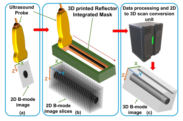
A metal reflector is set at a shallow angle inside the mask. Every frame catches it at a different depth, so the depth of that one bright line is the probe position. Drag the probe, and watch the readout follow.
Drawn for the prototype mask: 100 mm reflector, offset depth D = 5 mm, axial sample pitch dz = 18.48 µm, L11-5v probe at 7.60 MHz. Note the trade the angle forces. A shallow θ stretches a small depth range over a long track, which is what makes a long sweep possible, but it also multiplies any depth-estimation noise by 1/tan θ. The frame panel on the right is a schematic of the readout geometry, not a measured B-mode image.
Ultrasound pays for the third dimension twice
The transducer is cheap. Knowing where the transducer was is not.
A clinician reading 2D ultrasound has to hold a sequence of slices in their head and assemble the anatomy mentally. For a paediatric wrist fracture, or a limb being checked weekly through recovery, that mental reconstruction is exactly the part that varies between operators. 3D ultrasound removes it, but every route there has a bill attached.
A 2D matrix probe gives volumes directly and needs no position information at all, but the piezoelectric versions are expensive and hard to design, and even with cMUT fabrication the channel count, cabling and in-probe electronics remain difficult. Their small footprint also limits the field of view. Mechanical 3D probes motorise a linear array inside the housing, which again constrains the field of view, and motorised external stages are bulky enough to discourage routine scanning.
Freehand scanning with an external tracker is the flexible option. An electromagnetic tracker reads a receiver moving through a generated field, but is degraded by nearby magnetic sources. Optical tracking follows markers with two or three cameras, and gets more accurate as you add cameras, at the cost of stereo calibration error and yet more hardware. Both sit above $1000, which is the line at which point-of-care deployment stops making sense.
That leaves inferring position from the images themselves. Speckle decorrelation and learning-based trackerless methods read elevational displacement out of the tissue echo, so they inherit the tissue: they degrade where fully developed speckle is absent, inconsistent scan rates and angles produce non-smooth reconstructions, and the deep learning variants still need an EM or optical tracker to generate their training data in the first place.
A printed track that will not let the probe tilt
Non-contact freehand scanning, with the probe held parallel by construction.
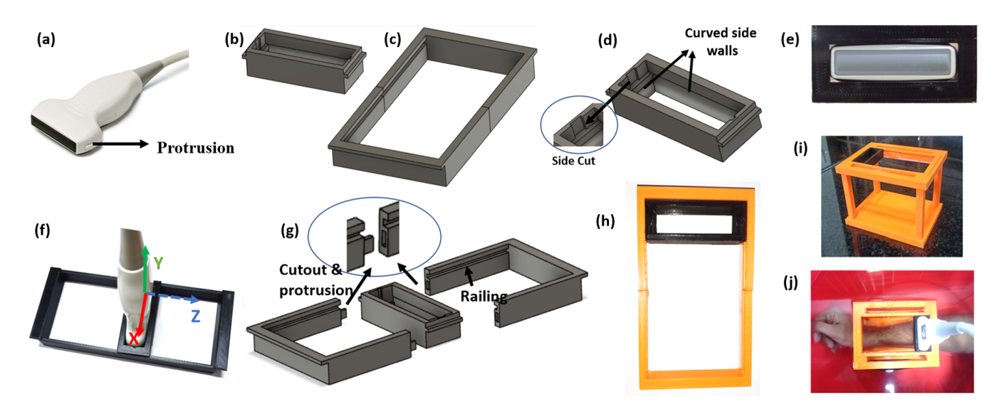
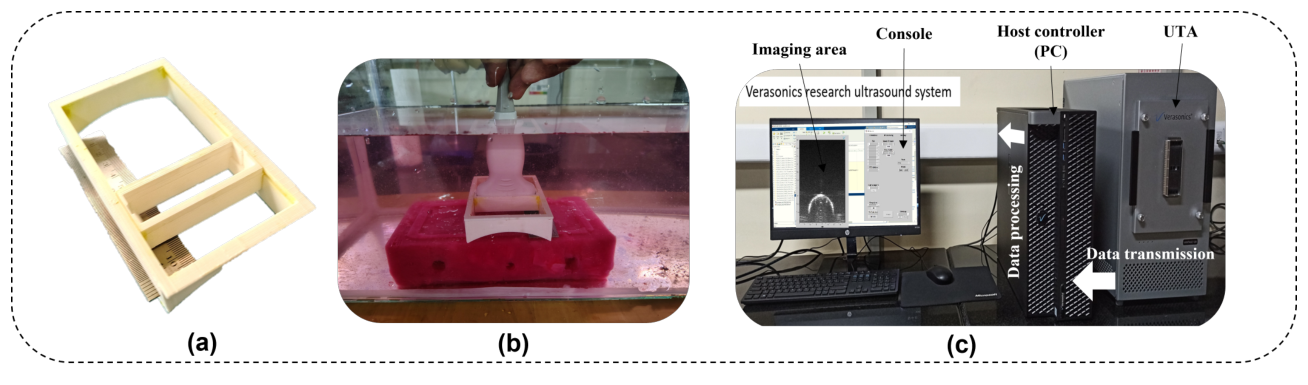
The mechanical track is drawn in Fusion 360 around the exact geometry of the Verasonics L11-5v, and can be redrawn for any probe. It comes in two parts. The probe mask is a bounding box with four curved side walls matching the probe body and side cuts that accept its protrusions, so the probe drops in and is pinned against tilt in x, y and z. The rectangular track carries a railing on its inner side walls that the mask rides along.
The mask is inserted between the two halves of the track, which are then joined, and that assembly is itself the locking mechanism: it stops the mask lifting vertically off the rail. Track blocks have a cutout at one end and a protrusion at the other, so blocks snap together and the scan length is whatever you build it to be, rather than whatever the housing allowed.
The track mounts to a stand, and the region being scanned is immersed in a water bath. Water is the couplant, so nothing presses on the tissue. For a live fracture or an open wound in a child, removing probe pressure is not a comfort refinement, it is what makes the scan possible.
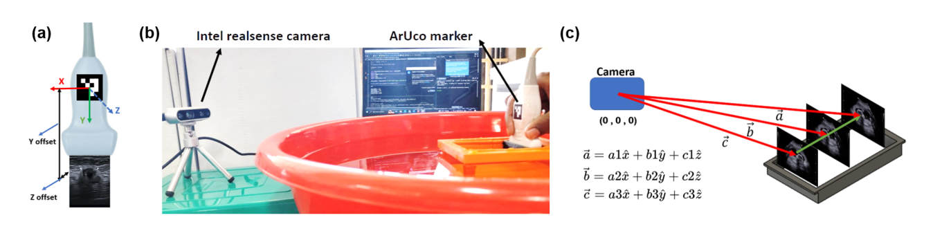
With tilt removed, one number remains: how far along the rail the probe has travelled. An ArUco marker is pasted on the probe and watched by an Intel RealSense D435 depth camera. The marker is found by edge detection, polygon extraction, a perspective transform to canonical form and Otsu thresholding of the resulting bit cells, then verified against the known pattern. Its centre gives x and y from the corner pixels with the camera matrix and distortion parameters; z comes from the depth sensor.
Because the marker sits on the probe and the probe cannot rotate, the image plane stays parallel to the marker frame with only a fixed translational offset, and reconstruction depends on relative motion between frames, so that offset drops out. Inter-frame spacing is then just the norm of the difference of successive position vectors.
The two systems are separate, so they drift. Absolute timestamps are collected from both at the same instant with millisecond precision, repeated 20 times, and averaged to fix the delay. Frames arrive at 100 fps from the ultrasound and at most 60 fps from the camera, and are matched on those timestamps.
| Experiment | X axis | Y axis | Z axis |
|---|---|---|---|
| 1 | 0.082 | 0.072 | 0.213 |
| 2 | 0.099 | 0.043 | 0.220 |
| 3 | 0.098 | 0.034 | 0.171 |
This table is the load-bearing measurement for the whole approach. It is what licenses the assumption of planar motion, and therefore what licenses replacing voxel-based, pixel-based or function-based reconstruction with plain linear interpolation.
From parallel frames to a volume in eighteen seconds
Constrained acquisition buys a simpler reconstruction, and a simpler reconstruction is what fits on an edge device.
The step that matters is the one that is missing. Freehand 3D reconstruction normally needs voxel-based, pixel-based or function-based methods, each of which carries a characteristic failure: voxel nearest neighbour throws artefacts when a voxel sits far from any frame, pixel nearest neighbour blurs when too many voxels are left empty, and function-based interpolation is accurate but computationally expensive. Because the track guarantees no two pixels in successive frames overlap, none of that is needed here.
The saving is measurable. Processing takes 18 seconds on an NVIDIA Clara AGX against 100 seconds on an Intel Core i5-1035G1, close to a sixfold reduction, which is the difference between a volume you wait for and a volume you scan again.
A goat tibia three times, then a human radius
Repeatability first, because an operator-independent claim is a claim about the second scan.
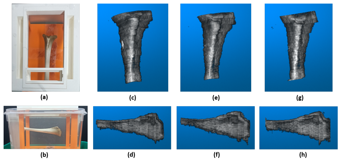
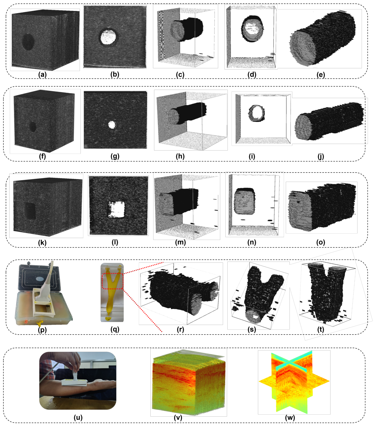
The ex-vivo study images a goat tibia in a water bath, at 256 × 190 pixels per frame. The U-Net was trained on 100 sample images of bone with ground truth marked by ultrasound experts, reaching an F1 of 0.85 on training data, and was then tested on a subject that did not appear in training. The whole experiment was run three times. Across those three repeats the average F1 on the test subject was 0.827, and the SSIM between corresponding frames from different runs holds a high median.
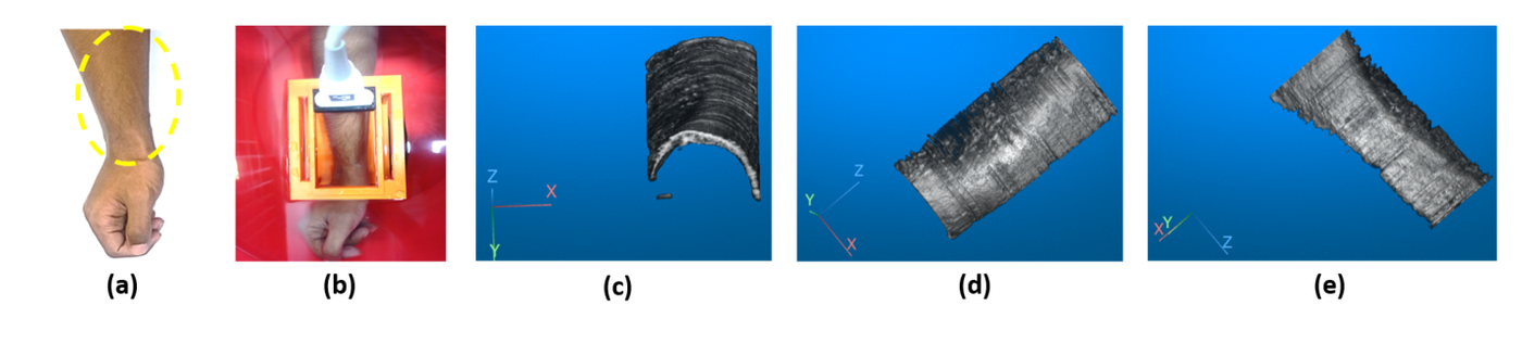
The in-vivo study images the radial bone of a human forearm. A U-Net trained on 100 cross-sectional images of the radius from multiple healthy individuals reached an F1 of 0.8241, and scored 0.809 on the test subject. The pre-processing chain runs unchanged: acquired frame, log compression, median filter, threshold, CLAHE, mask, segmented image.
Removing the camera as well
If the position can be read out of the B-mode image, no external sensor is needed at all.
The track still needs a camera watching a marker. The reflector integrated mask, or RIM, removes that too, and it does so without falling back on speckle. A slanted stainless steel reflector is built into the wall of an acoustic coupler. Because it sits at an angle, each frame along the sweep catches it at a different depth, and the depth of that one specular return is a direct measurement of where the probe is.
The distinction from trackerless methods matters. Speckle decorrelation and learning-based estimators infer elevational displacement from stochastic tissue echoes, so their accuracy is a property of the tissue in front of the probe. The RIM derives position from a deterministic target whose geometry is fixed by construction, which makes the position estimate independent of the tissue being imaged.
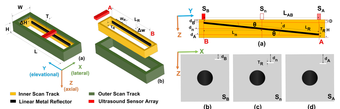
Two constants define the mapping, and a printed part will not hold either exactly. An error in the offset depth D turns out to be harmless: it adds the same shift to every frame, so the stack is displaced as a whole and the spacing between slices is untouched. An error in the angle θ is not harmless, because it scales every position, and a scaled stack gives wrong volumetric measurements.
So θ is measured rather than trusted. The mask goes into a water calibration box, the probe is placed at each end to read dA and dB, the physical separation LAB is measured with a digital vernier calliper, and θ follows from the arctangent of their ratio. It is a one-time procedure per mask.
A third case is a clinician sweeping faster than the system can resolve. The design bound follows from the smallest measurable step, but the measured behaviour is what should be quoted: scanning the 10 mm cylinder phantom at a range of speeds, location error stays low between 3.95 and 6.49 mm/s and then grows non-linearly beyond roughly 9.5 mm/s. Redundant frames landing on the same position are averaged rather than discarded, which improves that frame instead of wasting it. And because position is computed per frame rather than accumulated, a clinician may start the sweep anywhere on the track without affecting the result.
What neither approach has settled
Both designs buy their simplicity by giving something up. These are the invoices.
The track needs a water bath. Water as couplant is what makes the scan non-contact, and it is also what confines the method to anatomy you can immerse. Extending the design towards an enclosed scanner, closer in form to a CT gantry, is the route out.
The reconstructed volume has not been compared against a reference technique. The bone appears almost identical to the real one and the three repeats agree with each other, but repeatability is not accuracy, and the accuracy of the reconstructed volume against established methods is still to be evaluated. The track geometry is also currently fitted to one probe and one class of shape.
The RIM constrains motion rather than measuring it. It recovers position along one line. It does not recover probe rotation, tilt or in-plane translation, and it assumes a rigid gel-filled coupling path over an approximately planar surface. It is not a replacement for general freehand scanning; it is a repeatable, tissue-independent, GPU-free acquisition for anatomy where a linear sweep is clinically sufficient.
Positional precision is not the same as elevational resolution. The elevation beam width of an L11-5v is of the order of millimetres near its elevation focus and worse away from it, which is far coarser than the positional quantisation of the reflector readout. The honest statement of the result is that the RIM makes positional error negligible relative to the elevational point spread function, not that adjacent slices are independent.
The RIM manuscript is in preparation and its quantitative accuracy figures are still under revision, so no accuracy percentages are quoted on this page. The geometry, design parameters and calibration procedure described above are settled. Numbers will be added once the paper is submitted.
The papers behind this page
A Simplified 3D Ultrasound Freehand Imaging Framework Using 1D Linear Probe and Low-Cost Mechanical Track
Towards Multi-Perspective Panoramic Ultrasound Imaging Using Low-Cost 3D Printed Track And 1D Linear Probe
Sensor-Free 3D Ultrasound Imaging using Reflector Integrated Linear Guided Masks
The track running, and the volume being built
Two acquisitions compared frame by frame against the same scan taken freehand, and the reconstruction application working through a thousand frames.
Videos load from YouTube only when you press play, so nothing is requested from a third party until you ask for it.