3D-Printed Acoustic Masks
A concave shell printed in PLA, filled with a non-Newtonian gel, clipped onto a flat linear array. The transmit converges. The frame rate does not move.
improvement
improvement
attenuation
10 days
One radius, and the rest of the mask follows
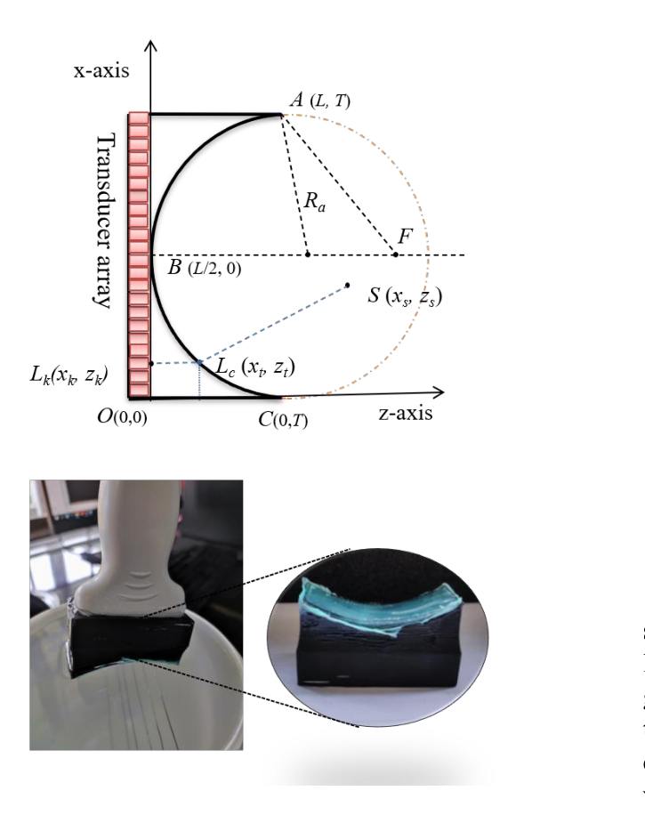
Pick a radius of curvature. Thickness, edge height and focal length are fixed by it, through the same two equations used to design the fabricated lenses.
Drawn for the fabricated configuration: L = 38.40 mm aperture, 128 elements at 0.30 mm pitch, collar thickness Tc = 10.00 mm. The depth axis rescales with the mask, so compare the labelled millimetres rather than the shape. cm = 1540 m/s in tissue and cl = 1595 m/s in the non-Newtonian fluid. The drawing is an illustration of the design parameterisation in the papers, not measured data. The simulated pressure fields further down are the measured convergence.
Focusing costs frame rate, and gel costs hours
Clinicians pick the probe to suit the depth. Linear arrays for the near field, convex probes for the far field. In both cases the transmit is focused with electronic delays, and that focusing caps the frame rate at roughly 50 fps, because every focal zone needs its own transmit event.
Plane wave imaging removes the cap by firing every element at once, but it gives up the focused transmit beam and the lateral resolution that comes with it. For a wearable system the trade is worse still: delays mean transmit events, transmit events mean time, and time on a moving body means motion artefact.
There is a second problem underneath the first. A rigid probe strapped to a curved surface makes imperfect edge contact, and the hydrogel filling the gap dehydrates within hours. Elastomer couplants last longer but damp the deep-tissue return. Continuous imaging with a conventional couplant is measured in hours, not days.
Move the focusing out of the electronics and into a passive part that clips onto the probe.
Nothing in the transmit sequence changes, so nothing in the frame rate changes either.A printed shell with a curved cavity
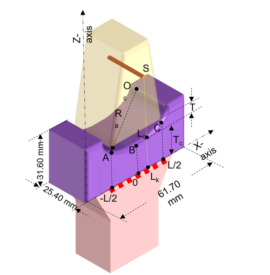
The mask is a rectangular polylactic acid shell, 60 mm by 25 mm by 31 mm, printed on an Ultimaker 2+ by fused deposition modelling with a 0.40 mm nozzle at 240 °C. PLA was chosen because it is non-reactive with the gel, rigid enough to hold the boundary of the lens, and biocompatible enough for prototyping against skin.
Its inner face is not flat. It carries a concave arc of radius 53.88 mm, a value taken from the range of human neck diameters. That arc is the whole optical design: with the fluid faster than tissue, a concave interface converges the transmitted plane wave instead of diverging it.
The curved cavity is coated with a thin latex sheet, then filled with the non-Newtonian gel using a squeeze bottle and levelled with a glass rod to the brim. Volumetric measuring cylinders keep the fill quantity uniform across lenses, which is what makes lenses of different radii comparable to each other at all.
Why a non-Newtonian fluid and not a gel pad
The filling is a saturated solution of polymerised sodium polyacrylate, a non-Newtonian fluid. It was chosen against three competing requirements that a solid lens cannot satisfy at once.
It has to be faster than tissue, or the concave interface diverges rather than converges. Measured by the direct speed-of-sound method at 7.6 MHz and 20 °C, it runs at 1595 m/s against the 1540 m/s assumed for tissue. Solid lenses reach a far higher speed of sound, up to 2680 m/s in reported designs, but they pay for it in impedance mismatch.
It has to be quiet. Attenuation of 0.238 dB/cm-MHz and an acoustic impedance of 2.0798 MRayls sit closer to tissue than the solid lenses in the literature, so less energy is lost reflecting off the lens boundary on the way in and on the way back.
It has to stay put. Its rheology holds the shape of the cavity, holds contact at the probe edges on a curved surface, and resists drying. That last property is what turns a benchtop trick into something wearable.
Speed of sound, attenuation and density measured at 7.6 MHz and 20 °C. The coupling-media paper reports 0.328 dB/cm/MHz for the same fluid used as a couplant rather than as a lens filling, across 4.60 to 10.60 MHz. Impedance and pH are from the coupling-media paper’s Table 1, where the conventional acoustic gel measured 1260 kg/m3 and 1.9656 MRayls at the same pH.
The beam converges, and the images follow
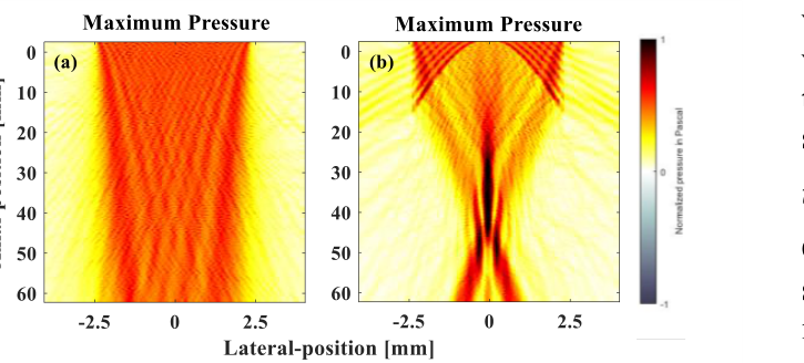
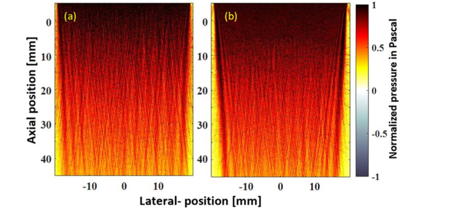
The convergence was checked first in simulation with k-Wave, recording maximum beam pressure over the axial and lateral planes for a 128-element array with and without the mask. The pre-focal region develops the tapered high-pressure zone that a converging wavefront produces, and it is absent without the lens.
Note what the reflected path does. The insonified wave converges, but the echoes returning through the gel-to-medium interface diverge, which is the transmit case run in reverse. The receive beamformer has to account for the refraction at the arc, so the two-way travel time is computed as three segments: through the lens at cl, out to the scatterer at cm, and back.
Then in water, then in a phantom, then in a person
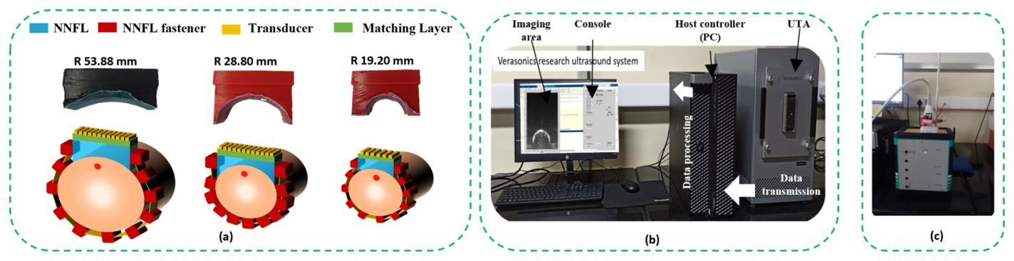
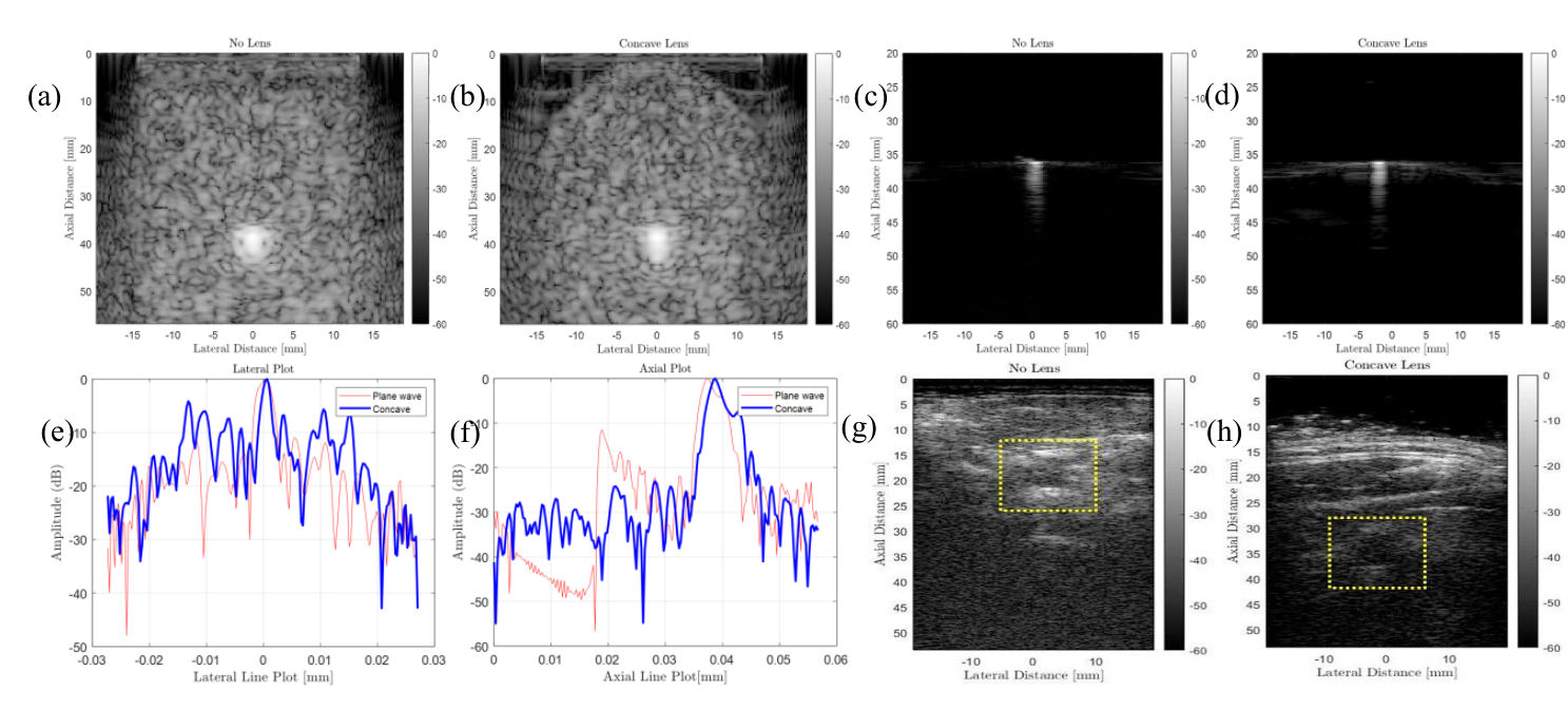
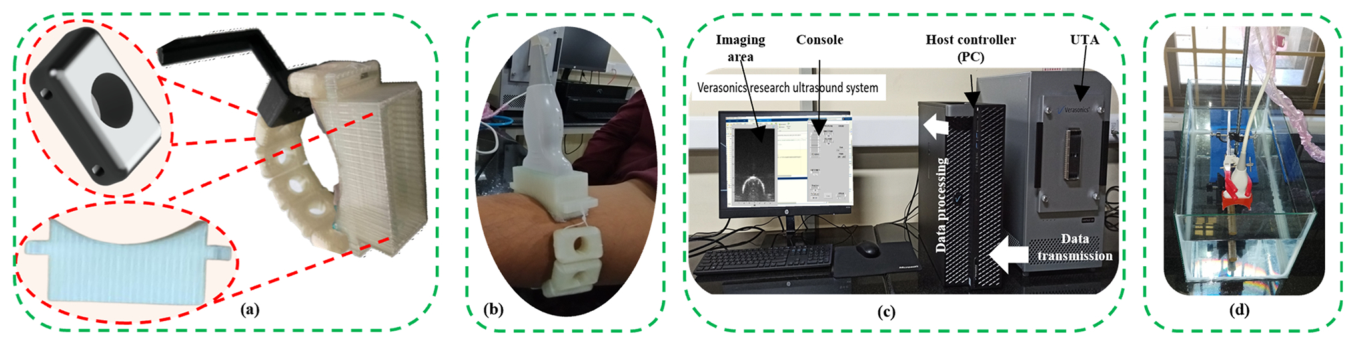
The experimental chain used an L11–5v linear probe on a Verasonics Vantage 128-channel system at 7.6 MHz centre frequency. Transmit was 51 plane waves steered from −18° to +18° in 0.72° steps, reconstructed with delay-and-sum. The targets were a wire phantom in water, a CIRS General Purpose Ultrasound Phantom Model 054GS, and in vivo the human carotid artery, upper arm and index finger.
No delay adjustment was applied to compensate for the known speed of sound inside the lens region. The authors note this would improve image quality further, which means the numbers below are a floor rather than a ceiling.
| Measurement | No lens | Concave lens | Improvement |
|---|---|---|---|
| Axial, simulation | 18 | 12 | 33.33 % |
| Lateral, simulation | 40 | 21 | 47.50 % |
| Axial, experiment | 1.7248 | 1.232 | 28.57 % |
| Lateral, experiment | 3.00 | 1.90 | 36.67 % |
Axial resolution gains less than lateral, and the papers are explicit about why: transmit frequency and bandwidth are unchanged, and the reconstruction is on a rectangular grid, so focusing is not expected to sharpen the axial direction.
Smaller radius, tighter beam
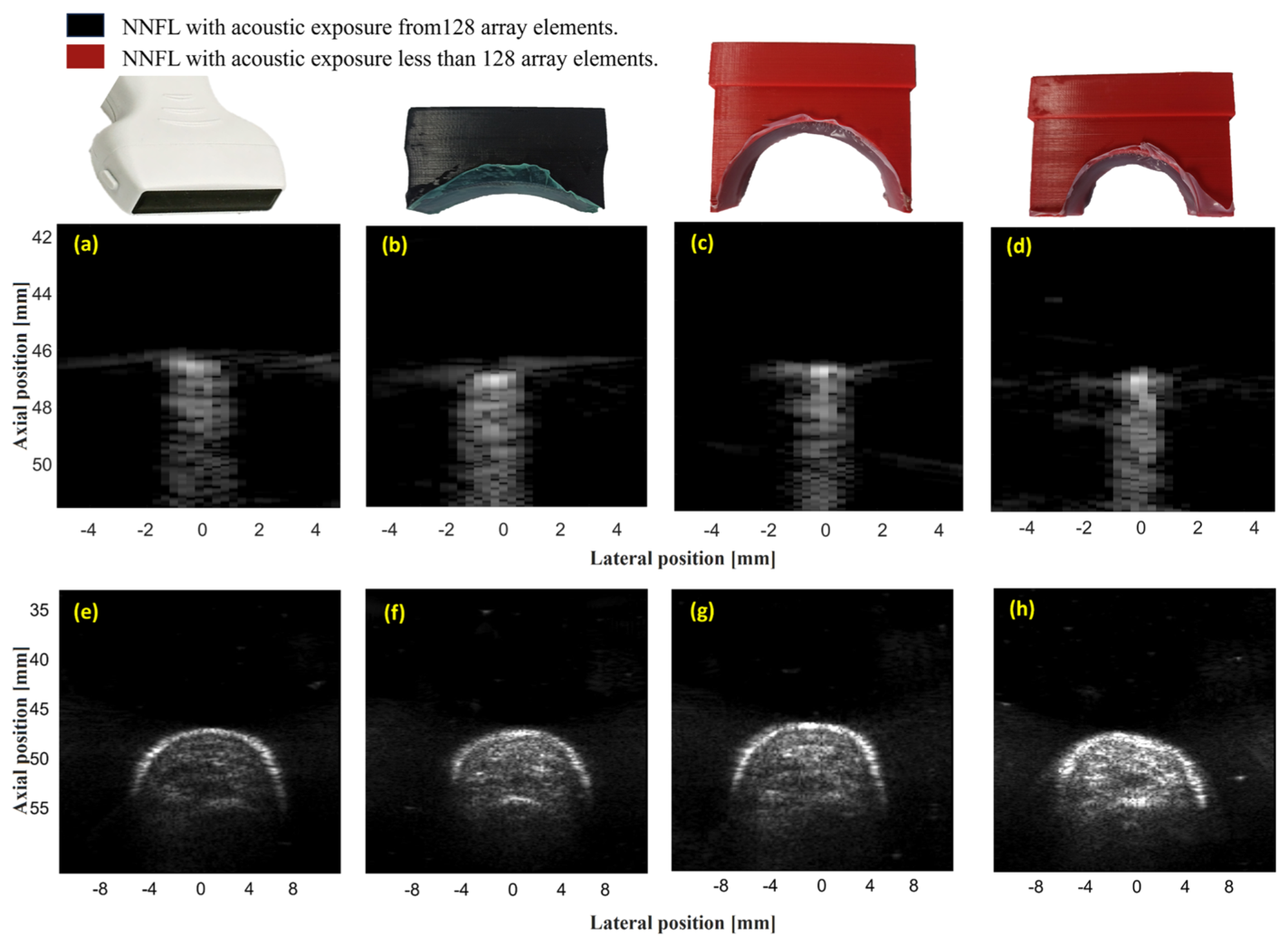
Three masks were fabricated at 53.88, 28.80 and 19.20 mm radius, printed in distinct PLA colours purely so they could be told apart on the bench. Across the sweep, clutter falls and intensity rises as the radius shrinks, which is the behaviour the geometry predicts and a useful handle for focused ultrasound applications. Contrast-to-noise ratio peaks at R = 19.20 mm and 7.60 MHz.
| Metric | Change with the lens |
|---|---|
| Lateral resolution, averaged over depth | 47.31 % improvement |
| Axial intensity | 44.57 % improvement |
| Contrast ratio | 54.33 % improvement |
| Contrast-to-noise ratio | 83.30 % improvementgreater than 3 dB |
| Peak near-field intensity | 15 to 20 % increasebelow 5 mm, where geometric focusing is minimal |
| Axial resolution | negligible change |
The near-field gain is not focusing. It comes from the interface: the fluid impedance of about 2.08 MRayls cuts transmission loss at the transducer boundary, and the concave profile shapes the beam weakly even before the geometry takes over.
Against the acoustic lens literature
What happens on day five
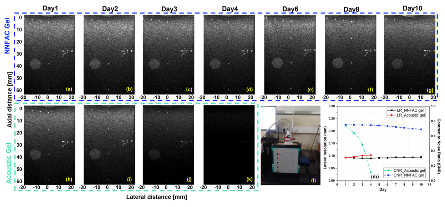
A lens that images well for an hour is a lens, not a wearable. The dehydration test put 5.00 g of the non-Newtonian gel and 5.00 g of conventional acoustic gel in identical printed masks, held at 20 °C with minimal airflow, and weighed both daily for ten days.
After ten days the fluid lens had lost 13.60 % of its mass. The acoustic gel had lost 50.40 %. In the parallel imaging series the difference shows up as a hard stop: B-mode images could be acquired with conventional gel only through day four, and from day five the gel had dried past usability. Lateral resolution and contrast-to-noise ratio for the non-Newtonian gel stayed essentially flat across the whole ten days.
The same fluid was also tested as a couplant in its own right, filling the gap between a rigid probe and a curved surface. On moulds imitating human curvature, lateral resolution improved by 35 % over conventional gel at the R 58.33 configuration, with a 3.5 % higher density that improves edge contact and makes trapped air bubbles less likely. Skin compatibility was checked over 24 hours of continuous contact, with no irritation, lesion, pigmentation or oedema, at a neutral pH of 7.

What the spherical arc still costs
The design ignores refraction and diffraction at the spherical geometry for simplicity. That simplification has a price: paraxial error across a spherical surface produces destructive interference between reflections arriving from different depths. Paraxial approximations in the design, or a metastructure lens in place of the plain arc, are the stated routes out.
The receive path leaves something on the table too. No delay adjustment compensates for the known speed of sound inside the lens, though the value has been measured. Folding it into the beamformer is a software change with no hardware cost.
The direction of travel is the same one the flexible array work is on. A passive part that upgrades an existing probe, rather than a new probe, keeps the wiring, the power budget and the frame rate exactly where they were.
In vivo imaging in this work was performed in line with the principles of the Declaration of Helsinki, and the coupling-media tests followed National Institutes of Health procedures.