NeedleTrack
In an in-plane insertion the needle should appear as a bright line on the B-mode image. Often it does not. The echo from the shaft is specular, its direction is fixed by the wavefront and the insertion angle, and at steep angles it never returns to the probe. This project studies how the choice of ultrasound transmission decides needle visibility in biopsies, nerve blocks and regional anaesthesia, and how the receive chain can be retuned to bring the needle back.
Deep Targets Force Steep Needles
Needle visibility in guided interventions is a geometry problem before it is an imaging problem.
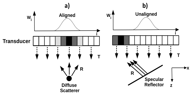
The insertion angle is not a free choice
In ultrasound guided interventional and regional anaesthesia procedures the needle is advanced within the imaging plane toward a target that typically lies within 70 mm of the surface. The angle follows from geometry: the deeper the target relative to the entry point, the steeper the insertion, with in-plane procedures normally performed below 45°. This study spans insertion angles of 15° to 50°, where the corresponding target depths run from roughly 11 mm to 56 mm.
The shaft is smooth and much larger than the wavelength, so it reflects like a mirror. Delay and sum reception weights elements by geometric proximity, and the directive specular return often lands on distant elements or leaves the array altogether. The needle is present, strongly reflective, and invisible. Failed visualization drives repeat insertions, tissue damage and bleeding, risks local anesthetic systemic toxicity, and lengthens procedures.
Hardware answers exist, echogenic coatings, roughened or sensorised needles, vibrating inserts, and clinicians largely avoid altering the needle. Tip detection alone cannot convey the trajectory, and image post-processing only works when part of the needle is already visible. The practical fix has to live in the transmit and receive chain of a standard scanner.
- Angles studied15° to 50° in-plane insertions
- Target depths≈11 mm at 15° up to ≈56 mm at 50°; typical procedures within 70 mm
- Failure modeSpecular return misses the DAS receive aperture
- ConsequencesRe-insertions, bleeding, local anesthetic systemic toxicity, longer procedures
Planar or Spherical: the Wavefront Decides
The same needle, the same receive chain, and two transmit physics with very different outcomes.
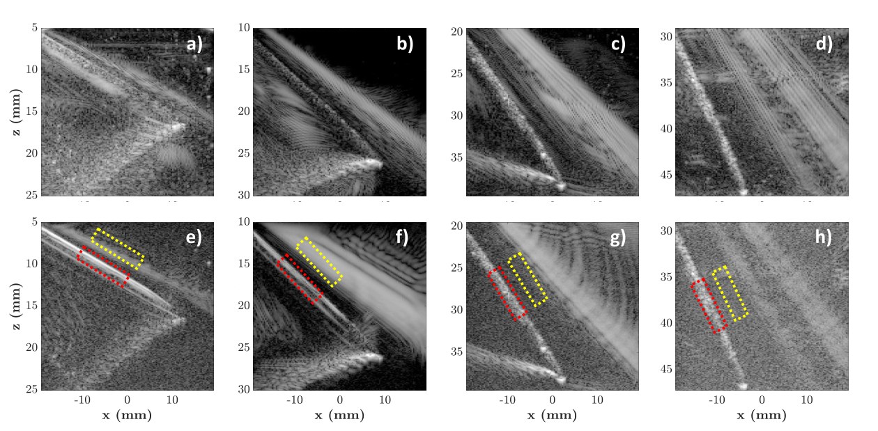
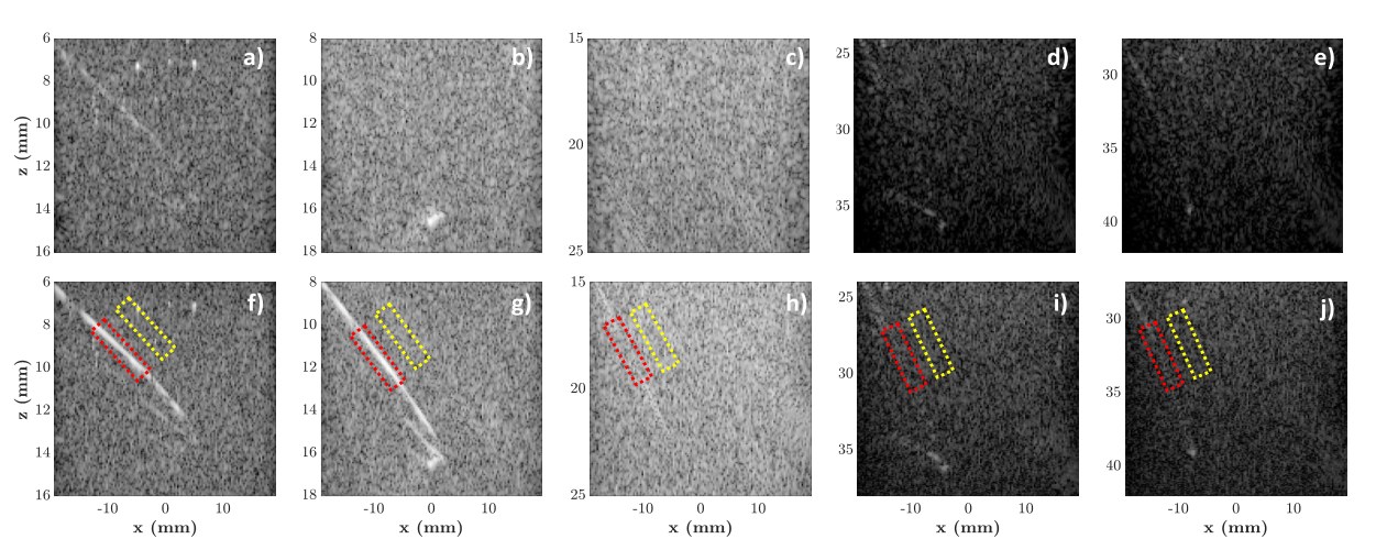
Spherical waves keep the needle on screen
Multi-angle plane wave imaging excites the full aperture at pre-decided steering angles, 73 of them between −18° and +18° here. Whether the needle returns energy depends on whether any of those discrete angles satisfies Snell’s law for the insertion at hand. Synthetic transmit aperture imaging instead fires one element at a time: each spherical wavefront meets some section of the shaft close to orthogonally, and adjacent transmissions overlap far more than steered plane waves do.
The difference is largest exactly where clinical insertions live. In the water bath at 20° the contrast ratio rose from 12.5 dB with plane waves to 33.3 dB with STA. With speckle noise added over the gel phantom the needle nearly disappears from plane wave images even at shallow angles, measuring −0.8 dB against 19.6 dB for STA at 20°. A directivity deviation measure confirms why: the specular energy stays far closer to the DAS receive window for spherical transmissions.
The advantage has a boundary. With depth the spherical wavefront diverges toward planar behaviour, and beyond about 40° both schemes watch the echo leave the aperture. Within that envelope the gain is free of computational overhead: needle visibility improves on the same real-time DAS pipeline the clinic already runs.
- AcquisitionVerasonics Vantage 128, L11-5v array, 128 elements, 7.6 MHz
- Transmissions73 plane waves −18° to +18°; 128 single-element STA
- CR, water 20°12.5 dB plane wave, 33.3 dB STA
- CR, speckle 20°−0.8 dB plane wave, 19.6 dB STA
- Best regimeInclinations below 40°, target depths to ≈26 mm
From Phantoms to Beef, From 15G to 21G
A method that only works on thick needles in water is not a clinical method.
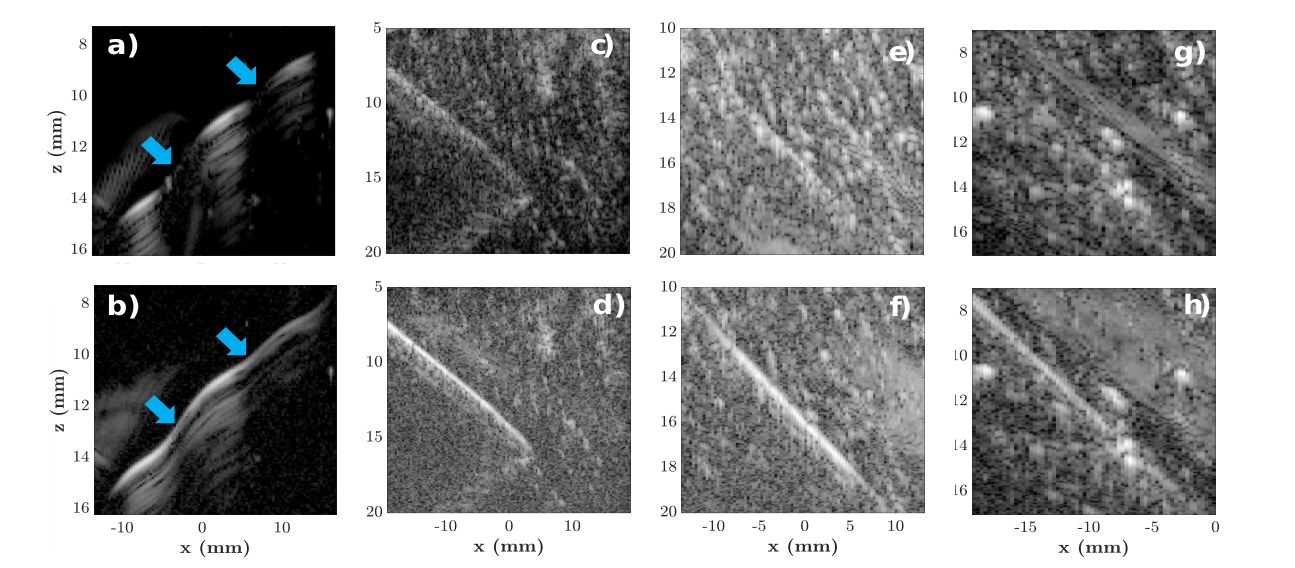
The thinner the needle, the more the transmission matters
A curved 0.80 mm copper wire in a gelatin phantom presents every incidence angle at once. Plane wave imaging reproduces it with gaps, the sections between 9.5 and 10.5 mm and between 12 and 13.5 mm appear as discontinuities, while the STA image captures the full curve.
In excised beef tissue, needles of 15G, 18G and 21G were inserted at random angles. Spherical transmissions render the shaft visibly better at every gauge, and the margin peaks for the thinnest: the 21G needle is hardly visible in the plane wave image while STA identifies the structure.
The point is practical. Transmission choice alone, with unmodified needles and the standard DAS receive chain, changes whether the needle can be followed in tissue. That helps the operator keep the needle in plane, or bring it back when it sways, with fewer transducer adjustments and a lower cognitive load.
- Wire phantom0.80 mm curved copper wire in food-grade gelatin
- TissueExcised beef, 6 cm cube, random insertion angles
- Gauges15G, 18G and 21G stainless steel needles
- Guide accuracyNeedle guide with an assumed ±2° error
When Steering Is Not Enough, Retune the Receive
Steep insertions defeat any fixed transmission. The Cognitive Ultrasound programme rebuilds the rest of the imaging chain around specularity, and each stage is detailed on its own page.
How planar and spherical wavefronts interact with an inclined shaft, characterised at the level of the channel data: the study behind Parts I to III of this page.
The Physics →Per-pixel vectors of reflected intensity separate specular interfaces from diffuse tissue and expose the directivity that magnitude images hide.
Characterisation →Sub-aperture directivity indexing detects specular pixels and overlays the optimal receive angle on the B-mode image as guidance for the operator.
Detection →The Radon transform of the channel data relocates the receive window, per pixel, onto the elements that actually catch the specular energy, preserving speckle.
Beamforming →Watch the Needle Come Back
Recordings from the experiments behind this work: live insertions, and reflection tuned apodization running against conventional DAS.


Explore the Beamforming Behind It
NeedleTrack is the clinical face of the Cognitive Ultrasound programme: the transmission physics above, and per-pixel specular beamforming beneath it.