Cognitive Ultrasound
Delay and sum assumes every echo is a diffuse reflection, and apodizes by geometric distance alone. Needles, bone and tissue interfaces are specular: their echoes obey Snell’s law and can steer clean off the aperture. This programme measures that mismatch, detects it per pixel, and rebuilds the beamformer around it.
Why Delay and Sum Loses the Needle
Before the beamformer can be corrected, the failure has to be characterised at the level of the transmitted wavefront and the received channel data.

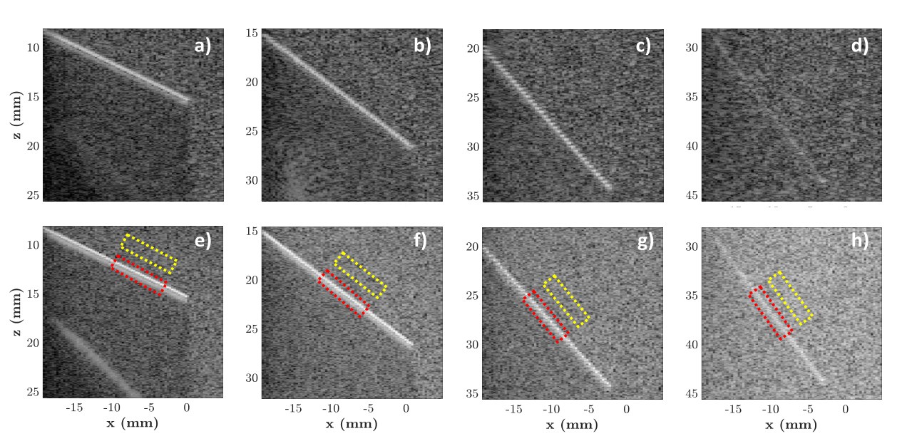
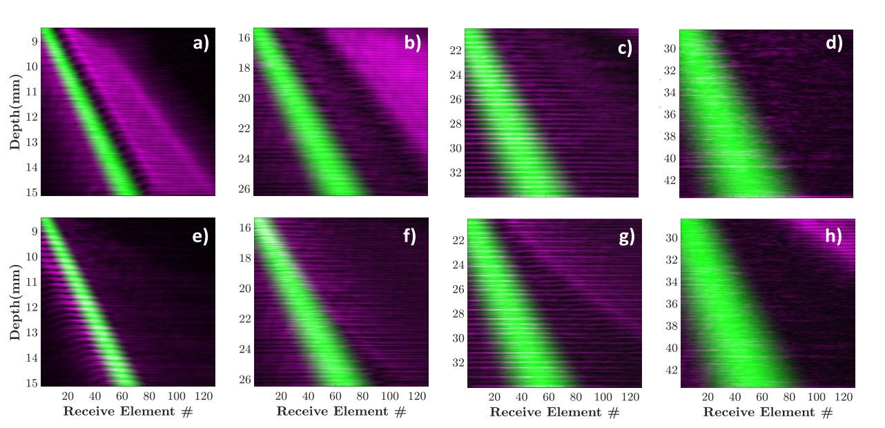
Directivity decides whether the echo ever returns
A diffuse scatterer is small relative to the wavelength and radiates weakly in every direction, so some energy always reaches the aperture. A specular interface, such as a needle shaft, a bone surface or the air–pleura boundary, is large and smooth, and reflects like a mirror.
The reflection direction is then fixed by the angle of incidence and the interface inclination. Steer the beam wrongly and the echo leaves the aperture entirely: the needle is physically present, strongly reflective, and invisible. Inaccurate localisation drives inadvertent complications and longer procedures.
- Governed bySnell’s law at the interface
- Depends onIncidence angle, interface inclination αg
- Studied withk-Wave simulation, water bath and gel phantom insertions
- TransmissionsPlane wave and synthetic transmit aperture
Reflection as a Vector Field
Conventional reconstruction collapses each pixel to a single number. Keeping direction alongside magnitude turns reflection behaviour into something you can see.
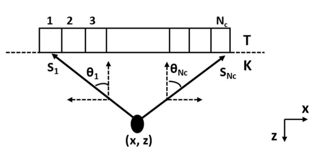

Magnitude alone hides the directivity
In DAS the delay-compensated signals are weighted by an apodization derived from geometric distance and summed into a single scalar. Any directivity the reflection carried is suppressed by that weighting before it is ever measured.
Treating the reflected intensity from each pixel to each element as a vector produces a field mapping the pixel into the transducer plane. A diffuse pixel yields a broadly uniform field regardless of transmit angle. A specular pixel yields a field that is strongly non-uniform and converges according to the incident wavefront and surface orientation.
Applied to the lung, the same construction separates a normal air–pleura interface from edematous and consolidated models, where increased density and reduced air push the interface from specular toward diffuse.
- ArrayL11-5v, 128 elements, 0.3 mm pitch, 3.84 cm width
- Transmit−18° to +18° at 0.5° resolution, 73 plane waves
- Centre freq.7.6 MHz, sampled at 31.25 MHz, c = 1540 m/s
- Validated onGelatin wire phantom, in-vivo back palm, k-Wave lung models
Finding Specularity, Then Telling the Operator
Characterisation becomes clinically useful only when it closes the loop back to the person holding the probe.
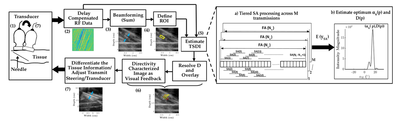
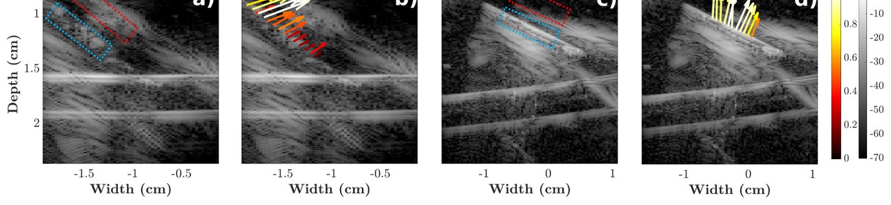
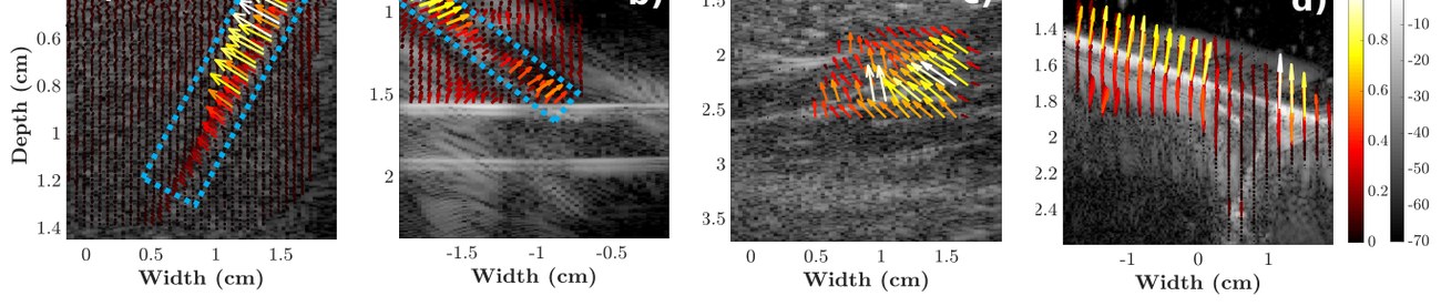
One beam cannot resolve direction, many sub-apertures can
A full-aperture beamformer produces a single beam per pixel, which is not enough to recover where the energy came from. Sub-aperture processing forms many beams per pixel instead, each looking from a different receive angle, across every transmission.
For a specular pixel the reflected intensity peaks sharply in the sub-apertures satisfying the transmit–receive relation and collapses elsewhere. That peak yields a directivity value and the optimal receive angle with its transmit angle, which are resolved into a vector and overlaid on the B-mode image as operator feedback.
The operator can then recognise specular data patterns and recalibrate probe placement or transmit steering so reflections return within the aperture, rather than relying on anatomical intuition alone.
- EstimatesDirectivity value D(p) and optimal receive angle
- AcrossTiered sub-apertures × all transmissions
- OutputDirectivity-characterised overlay on the B-mode image
- Validated onSimulated +45° reflector, needle, brachioradialis, bone
Reading the Radon Transform to Reshape the Aperture
If the reflection pattern can be read directly from the raw channel data, the receive window can be built to match it, one pixel at a time.
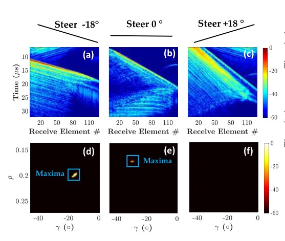
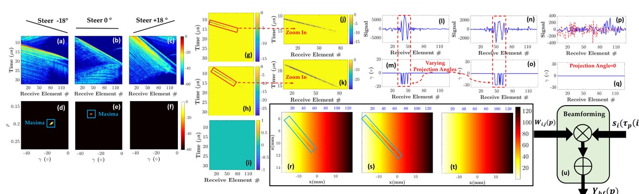
The aperture should follow the reflection, not the geometry
Conventional apodization weights each element by its geometric distance to the pixel, which is the correct thing to do only if the reflection is diffuse. Beamformers built specifically for specularity fix that, but suppress diffuse speckle in exchange, forcing separate imaging modes for tissue and for needles.
Reflection Tuned Apodization avoids the choice. The Radon transform of the received RF data exposes the orientation of the reflection at every depth: a specular return produces a sharp maximum in the sinogram whose projection angle correlates with the reflection angle, while the shift in that signature measures the deviation from the geometric model.
From those maxima a projection map is estimated per transmission, time-of-flight compensated into the pixel domain, and used to translate the apodization window onto the elements that actually receive the specular energy. Diffuse pixels are unaffected, because for them the optimal set is already the geometrically nearest one, so specular structure is recovered without losing speckle texture.
- ReadsRadon transform of the raw RF data
- EstimatesOptimal projection angle γ per pixel and transmission
- Acts onReceive apodization window centre, per pixel
- PreservesDiffuse speckle alongside specular structure
- Validated on15G needle at 15°, 20°, 30° in water bath and in speckle
Trading Contrast Against Resolution, Deliberately
Between a cheap beamformer with low contrast and an expensive one that distorts dynamic range, there is a tunable middle.
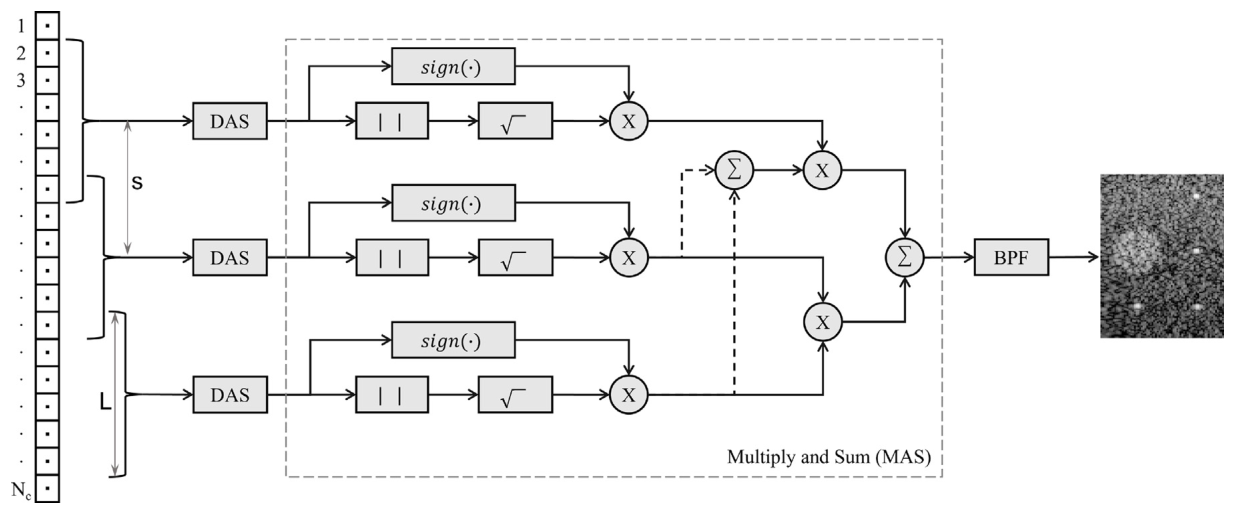


One continuum from DAS to F-DMAS, with a cost dial
Beam Multiply and Sum sits between delay and sum and filtered delay multiply and sum. Rather than cross-multiplying raw channel signals, it cross-multiplies already-beamformed sub-aperture beams, which is far cheaper and preserves a linear relationship with the theoretical intensity gradient instead of the non-linear dynamic range compression that F-DMAS introduces.
Two knobs set the behaviour. With the sub-aperture spanning the full aperture, BMAS approximates DAS; reduced to single elements it becomes F-DMAS; between them it moves smoothly. Shrinking L sharpens lateral resolution and contrast but increases vulnerability to off-axis interference and speckle loss. The stride sets how many sub-apertures exist, and so the arithmetic cost per pixel.
On the dynamic range phantom, whose gradient region has a theoretical slope of −2.50 dB, BMAS measured −2.51 dB. The comparisons came in further away: −2.39 dB for single plane wave DAS, −2.35 dB for MVDR, and −2.46 dB for 75-angle compounded DAS.
- KnobsSub-aperture length L, stride s
- SpansDAS at one extreme, F-DMAS at the other
- Slope vs −2.50 dBBMAS −2.51, DAS −2.39, MVDR −2.35, DAS75 −2.46
- Evaluated onPICMUS in-silico and in-vitro datasets