Project · Ultrafast Ultrasound

Ultrafast Ultrasound based Flow Imaging

Most blood vessels run parallel to the skin surface, so the flow is transverse and conventional Doppler estimates are not reliable. We build beamforming and velocity estimation methods that recover the full velocity vector from non-steered plane waves, at frame rates fast enough to follow flow transients.

left Rx aperture right Rx aperture 128-element linear array depth < ZL directional BF cross correlation no angle estimator needed depth > ZL triangulation · STDMR autocorrelation (x, z) α₁ α₂ 0 15 30 [mm] non-steered plane wave transmit

Schematic redrawn from the fusion beamforming paper.
ZL = 15 mm in simulation, 15.4 mm experimentally at F# 1.71.

10 kHzPlane wave PRF, in-vitro
05.42%Velocity magnitude bias, fusion
4Peer-reviewed papers
Project Objectives

What This Project Sets Out To Do

Two objectives run through every result on this page: realistic flow models to test against, and beamforming that makes the velocity estimate worth trusting.

Simulation & Phantom Models

Flow phantoms generated in Field II with parabolic and gradient profiles at different velocities and flow directions, alongside in-vitro rotating disk and flow pump datasets acquired on a Verasonics scanner.

Beamforming for Flow

Non-linear high resolution beamforming, dual apodization at receive, and depth aware fusion, all built for non-steered plane wave transmit so the frame rate stays high.

Vector Velocity Estimation

Triangulation with autocorrelation and directional beamforming with cross correlation, compared head to head under the same acquisition so the beamformer is the only variable.

Transient Sensitivity

Validation against events, not just steady profiles: air bubble tracking, a sudden reversal of flow direction, and pulsatile flow in an in-vivo carotid artery.

Animation of a typical ultrasound based flow imaging system
A typical ultrasound based flow imaging system.

Conventional Doppler is least sensitive to the transverse component of flow velocity, so the estimate depends heavily on the beam to flow angle. Every method here is built to remove that dependence.

Work Done

Three Beamforming Approaches

Each approach targets a specific failure mode of conventional vector flow imaging. Figures are taken from the published papers listed below.
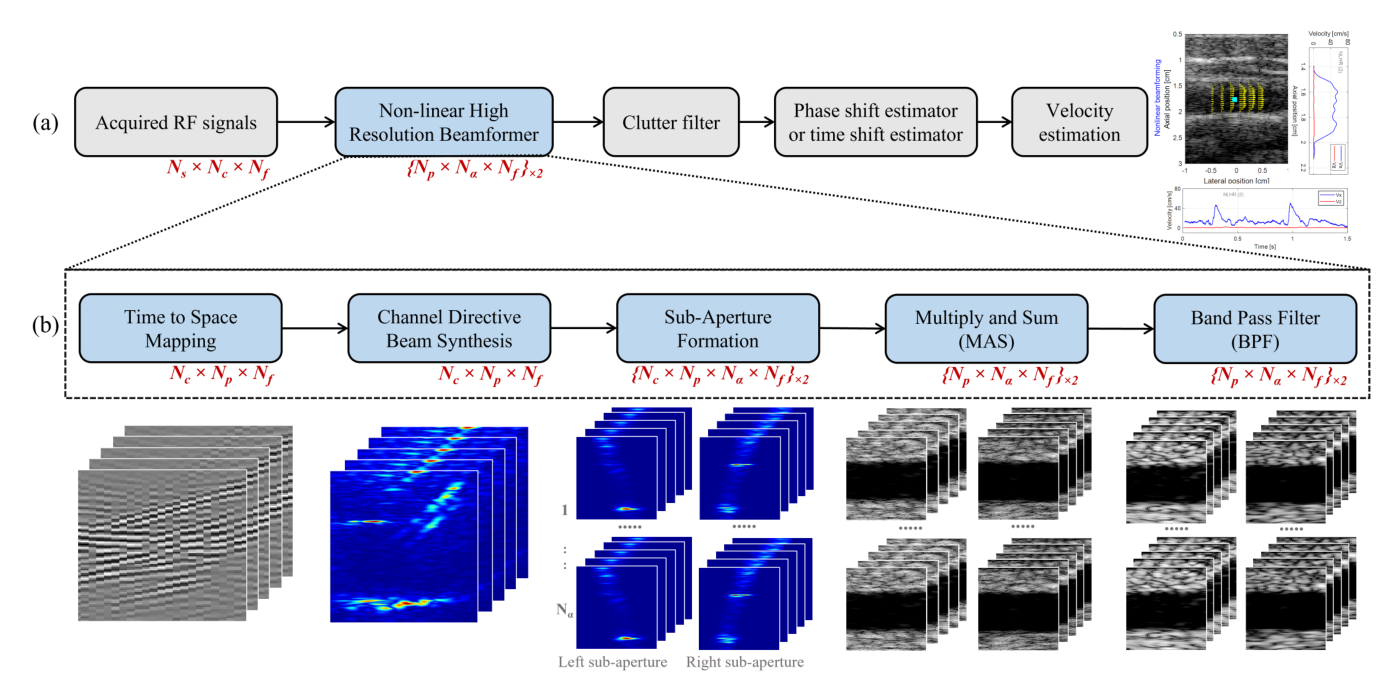
Block diagram of the non-linear high resolution beamforming pipeline for flow imaging
NLHR pipeline. Acquired RF signals pass through the non-linear high resolution beamformer, clutter filter, phase or time shift estimator and velocity estimation. The beamformer itself performs time to space mapping, channel directive beam synthesis, sub-aperture formation, multiply and sum, and band pass filtering. From the Computers in Biology and Medicine paper.
Non-linear Beamforming

Non-linear High Resolution (NLHR) Beamforming

The conventional delay and sum beamformer is used almost everywhere in flow imaging because it is cheap, but it offers poor contrast, low imaging resolution and limited spatiotemporal sensitivity. Inspired by the F-DMAS beamforming in B-mode imaging, this work attempts to address the spatiotemporal sensitivity of the conventional flow imaging techniques with a novel non-linear beamforming approach, without the use of any contrast agents and deep learning based methods.

The gain comes from harmonic generation and enhanced coherence in the beamformed signals, which is what sharpens sensitivity to flow transients.

  • A novel nonlinear beamforming technique is proposed for ultrasound flow imaging, and the first effort towards the application of nonlinear beamforming in flow imaging.
  • The beamformer is validated using typical parabolic flow simulations with a cross-correlation based velocity estimator and an autocorrelation based velocity estimator, which are the common velocity estimation techniques in the literature.
  • Velocity sensitivity is investigated with in-vitro datasets including a rotating disk, air bubble tracking, and flow direction reversal, followed by in-vivo performance evaluation on a typical pulsatile flow in a carotid artery dataset.
  • Compared to state-of-the-art DAS based flow imaging approaches, the results suggest better spatiotemporal sensitivity towards the flow transients.
See the result videos
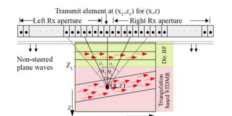
Schematic of the depth aware fusion beamforming approach showing left and right receive apertures and the limiting depth
Depth aware fusion. Above the limiting depth ZL the region is beamformed directionally; below it, triangulation based STDMR is used. From the IEEE EMBC paper.
Fusion Beamforming

Angle Independent Depth Aware Fusion

In vector flow imaging systems, the most common beamforming techniques employed are the directional beamforming based cross correlation and the triangulation-based autocorrelation. However, the directional beamforming-based techniques require an additional angle estimator and are not reliable if the flow angle is not constant throughout the region of interest. On the other hand, estimates with triangulation-based techniques are prone to large bias and variance at low imaging depths due to limited angle for left and right apertures.

The hypothesis behind the proposed approach is that the peripheral flows are transverse in nature, where directional beamforming can be employed without the need of an angle estimator, and the deeper flows being non-transverse and directional, triangulation-based vector flow imaging can be employed. The switch is made at a limiting depth ZL set by the F-number and the receive aperture size: 15 mm in simulation, and 15.4 mm for the experimental study at an F-number of 1.71.
Velocity magnitude bias, simulation study
Directional cross correlation21.46%SD 6.26%
STDMR triangulation16.74%SD 6.98%
Fusion beamforming05.42%SD 6.24%
0%bias →25%
  • Overall 67.62% and 74.71% reduction in magnitude bias against triangulation and directional beamforming respectively
  • Simulated in Field II at an 8 MHz transmit centre frequency and 0.1925 mm wavelength, with ten ensembles of 16 frames
  • In-vivo data acquired on a Verasonics Vantage system at 10,000 frames per second with a 128-element L11-5v probe at 7.6 MHz
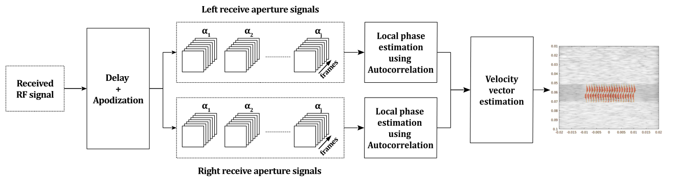
Block diagram of the dual apodization based triangulation pipeline with left and right receive aperture signals
Dual apodization in triangulation. Received RF is delayed and apodized, then left and right receive aperture signals feed local phase estimation by autocorrelation before velocity vector estimation. From the IEEE ISBI paper.
Triangulation & Apodization

Non-steered Plane Waves and Dual Apodization

Most vector flow strategies steer plane waves electronically at several angles. Here the transmit stays non-steered and the angle diversity is recovered at receive. A triangulation algorithm makes a best fit out of the estimates obtained with different receive angles, which reduces the variability of the vector estimate with receive angle.

The dual apodization work takes this further, using multiple apodization to induce a steering effect at receive along with sidelobe suppression on the delay compensated RF signals. Simulations for transverse flows at different profiles and velocities show improved resolution and better clutter suppression.

  • Error variance in velocity magnitude as low as 5.0251 × 10⁻⁴ [m/s]2 with Hanning-Gaussian apodization
  • Mean angle error of +0.7358° for a transverse gradient flow at a peak velocity of 0.25 m/s
  • Field II simulation at a 3 MHz transmit centre frequency, 192 active elements, wavelength 0.5133 mm
Validation

In-vitro and In-vivo Results

Results shown here are reproduced from the papers. The in-vitro rotating disk dataset was acquired on a Verasonics scanner with a 128-element linear array under non-steered plane wave insonification at a 5 MHz centre frequency and a 10 kHz pulse repetition frequency.
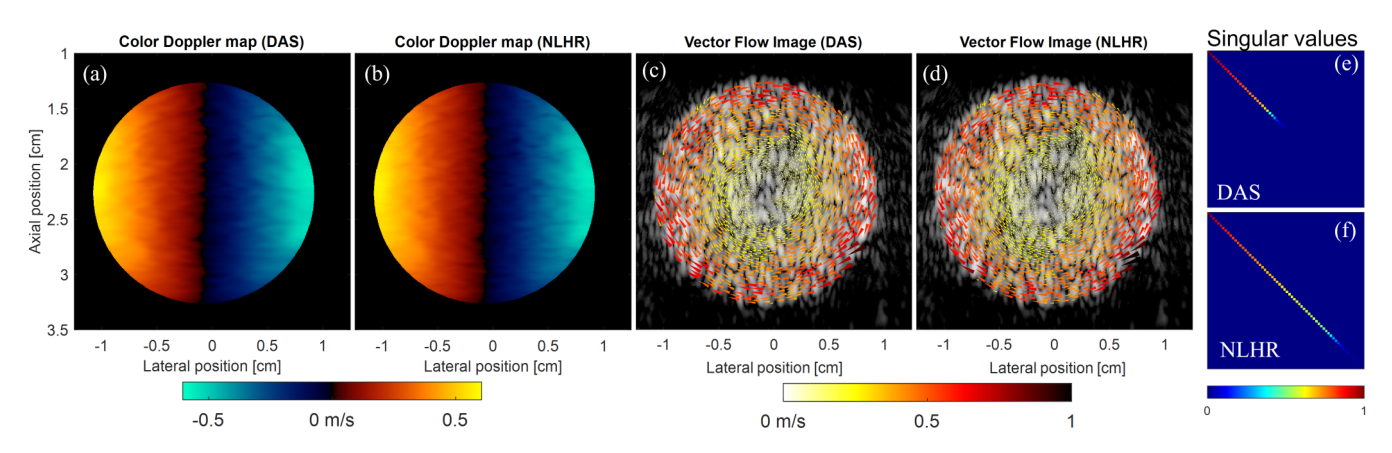
Colour Doppler maps and vector flow images of a rotating disk for DAS and NLHR beamforming, with singular value plots
Rotating disk, DAS against NLHR. Colour Doppler maps (a, b), vector flow images (c, d) and singular values (e, f). No clutter filter was required for this dataset.
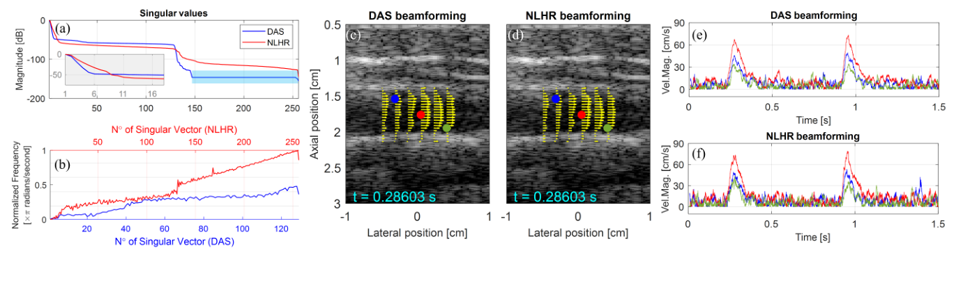
In-vivo carotid results comparing DAS and NLHR beamforming with velocity magnitude traces
In-vivo carotid, pulsatile flow. Singular value magnitudes, DAS and NLHR beamformed frames with overlaid velocity vectors, and the corresponding velocity magnitude traces over time.
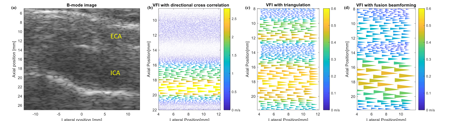
In-vivo carotid bifurcation B-mode image and vector flow images from directional cross correlation, triangulation and fusion beamforming
Carotid bifurcation, three beamformers. B-mode image of the region of interest with the external and internal carotid arteries marked, then vector flow images from directional cross correlation, triangulation, and fusion beamforming.
Animated rotating disk result for non-linear beamforming
Rotating disk, animated. Non-linear beamforming applied to the rotating disk sequence.
Figure reels from the papers
Animated reel of figures from the non-linear beamforming paper
NLHR beamforming reel. Cycles through the beamforming pipeline and the flow phantom pulsatile results (Fig. 14): singular value magnitudes, vector flow images for DAS and NLHR, and velocity magnitude and angle profiles over time. The captions are part of the original figures.
Animated reel of figures from the fusion beamforming paper
Fusion beamforming reel. Cycles through the depth aware beamforming schematic (Fig. 7) and the fusion imaging simulation results (Fig. 19): B-mode of the region of interest, vector flow images for directional cross correlation, triangulation and fusion, and the mean estimated velocity comparison. The captions are part of the original figures.

Still figures are cropped directly from the published papers. Detailed results for every test case in simulation, phantom and in-vivo studies are available as supplementary material with the journal article.

Media

Result Videos

Eight video results for the non-linear beamforming test cases, from the NLHR Beamforming for Flow playlist.

Scroll for all eight

Tracking of simulated pulsatile flows having five distinct impulses of different durationsSimulation

Tracking of simulated pulsatile flows having five impulses of different velocity changesSimulation

Non-linear Beamforming for In Vivo CarotidIn-vivo

Non-linear Beamforming for Air Bubble TrackingIn-vitro flow phantom

Non-linear beamforming results for flow Direction ReversalIn-vitro flow phantom

Non-linear beamforming for typical Pulsatile FlowIn-vitro flow phantom

Rotating Disk B-mode – DAS Vs Proposed NLHRIn-vitro rotating disk

Rotating Disk Color Doppler – DAS Vs Proposed NLHRIn-vitro rotating disk

Interested in ultrafast flow imaging?
Get in touch with the group, or browse the wider set of ultrasound projects.